Within the last few decades, the amount of electrical equipment aboard boats has increased enormously in both quantity and sophistication. Some would argue that electric lights, radios and navigators are essentials, but what use is any of it without electrical power? On most boats, the main source is the engine alternator which typically provides around 100 times the output of a solar panel, wind or prop shaft generator. Clearly the alternator is a key component but in contrast to the amazing advances that have been made in other areas, battery charging systems remain basically the same as those in use half a century ago. In essence, alternators are simple devices, not difficult to understand, and most faults can be fixed with no more than basic tools and simple electrical skills. In this article we will not be looking at specific models, but alternators in general. Understanding their working principles and being able to recognise parts and wiring should put you in a position to tackle most common problems, even on a type you have never seen before.
FIRST PRINCIPLES.
When a magnet is passed over a wire, an electric current is produced in the wire. With just one wire and a small magnet, the effect is hardly noticeable but useful amounts of electricity can be made by increasing the strength of the
magnet and by using a coiled wire. In alternators, this is increased still further by using several coils connected together (ie. stator wingdings) and by using a large electromagnet (ie. field magnet) with multiple north and south poles.

Fig 1. Alternator details
The field magnet is formed by passing a current (via brushes and slip rings) through a coil of wire around the iron core of the rotor. The reason for using this instead of a simple permanent magnet is that, by varying t. he current through the coil, the strength of the field and hence the alternator output, can also be varied. This is important as, without control of the output, there would be a risk of damaging the battery through overcharging.The main coils in which current is generated are wound between slots on the inside of a laminated iron ring, forming the stator and main body of the alternator. At first sight, you see what looks like an intricate set of interconnected copper coils. Some overlap each other and all are tightly bound and varnished together, making it hard to see exactly what is connected to what. None the less, it’s not hard to recognise the layout, once you know what to look for.

Fig 2 Stator layout.
The arrangement shown in fig 2 is typical. All alternators have three separate sets of stator windings, each consisting of several individual coils joined in series. (In fig 2 there are 6 but other types have 6 more reverse wound coils
occupying the spaces between those shown.) When the stator is assembled, one complete set is laid down first, then following sets are laid on top but with individual coils slightly to the side of those in previous layers. Fig 2 also
shows the two ways, star and delta, in which windings can be connected. Technical differences between the two need not concern us, though when checking windings for faults, it’s useful to know which type you are dealing with.
As their name would suggest, alternators produce alternating current (AC). Its direction changes as alternate north and south poles of the field magnet pass over each coil and this is no good for battery charging which requires a direct current (DC). Changing AC to DC is the job of the diodes. These are small, cylindrical devices, arranged in groups of three and mounted on an aluminium or copper plate just beneath the alternator back cover. They act as electrical non return valves, only allowing the current to flow in one direction, but unfortunately they are not quite perfect and consume a little energy themselves. This is dissipated as heat through their mounting plate, sometimes aided by cooling fins.There are always 6 main diodes, which are often arranged in two groups of three. Diodes within the groups are identical but the group connected to the negative terminal is likely to be assembled from diodes whose body is their anode connection. This is simply for the convenience of being able to bolt all three to the same heat sink. Diodes connected to the positive terminal have the reverse configuration.
Fig. 3 Diode types and connections.
CONTROLLING THE OUTPUT
The term voltage regulator is a little misleading as its purpose is really to control charge current. It does this by monitoring the voltage in the output supply lines. If their voltage is low, say about 11 volts, it responds by sending more current to the field coils. This increases their magnetism which in turn causes the alternator to pass more current to the battery. As it becomes charged the battery terminal voltage increases a little and this is detected by
the regulator which reacts by reducing the field current and hence the alternator output. Most regulators in use on boats today are sealed pieces of electronics, usually located beneath the rear cover though, on some types, it is in a separate, externally connected unit. Most regulators used on boats were designed for road vehicle applications but on boats they are not good at bringing a nearly flat battery quickly up to full charge. To make up for this shortcoming, several firms have produced “marine” types with improved characteristics. However, we will leave the comparison for another day since, at a pinch, any alternator can be made to function without either sort (more on this later), and this is good enough for our purposes here..Regulators fall into two categories which are not interchangeable. These are called “N” and “P” types, and for trouble shooting purposes it’s useful to be able to recognise which type you have, which means tracing the regulator and field coil connections.Fig 4 gives the details.
Fig. 4. Regulator connections.
TROUBLE SHOOTING.
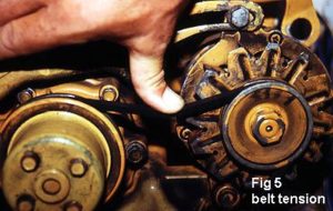
Most alternator difficulties are not caused by obscure electrical problems but simple faults like bad connections or not having the drive belt tension correctly adjusted. Too much slack will cause the belt to slip so output current will be low and batteries slow to charge. As it slips, the belt may make a characteristic squealing noise and throw off sooty black particles of rubber. In bad cases the drive pulleys will become overheated and eventually, the belt will smoke and burn. Too much tension is just as bad and damages the belt as well as the end bearings of the alternator and any other item driven by it (eg. water pump). If the belt is actually broken, it is hard to get by without an exact replacement. The the type of segmented belt that can be taken apart and rejoined to make any required length is a useful standby, though in the absence of this, don’t rely on the idea that a knotted length of cord or pair of tights will do instead. After checking the belt and before looking further into any alternator problem, make sure that all ancillaries eg. batteries, warning light key switch, and their associated wiring is in good order. You could be saved a pointless strip down or trip to the repairers. Having completed the preliminaries and ruled out all the easy to fix faults, it’s time to delve a little deeper into the works, but let’s check the easier things first.
BRUSHES AND SLIP RINGS
Brushes are normally mounted in a detachable plastic holder, located beneath the back cover. If space around the engine is not too restricted you may be able to remove the cover and brush holder without taking out the alternator as a whole. With the brush holder out, check that the brushes are not worn, can move freely in their holder and that the securing spring pressure is sufficient to hold them firmly against the rotor slip rings. Whilst the brushes are out take a look at the slip rings at the same time. This is easier if the alternator is out of the engine but if they are only slightly discoloured and not deeply grooved (possibly due to worn brushes) then leave them alone. If you dismantle the alternator, carefully clean away any baked oil or grease with a fine abrasive. In an emergency, fairly satisfactory replacement brushes can be made by taking the brushes from an an electrical appliance like an electric drill, sander or vacuum cleaner. The chances are that none of these will be a direct fit in the alternator brush holder but just so long as they are not too small to begin with, this type of carbon brush is easily sanded down to size.
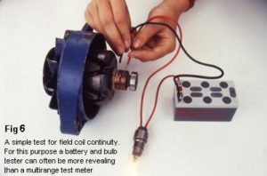
Fig. 6. Testing the field windings.
TESTING THE FIELD WINDINGS
Volt/ohm/amp, multi-meters are useful for many electrical checks on boats, but when measuring voltages to look for broken circuits, their high sensitivity can confuse the results. Alternator windings have a resistance of only a few ohms which most multi-meters are unable to distinguish from a short circuit. For these purposes, a simple battery and test lamp is a good tool to use and is easily assembled from bits likely to be found on board. Photo 2 shows a small 12 volt battery (could have been a collection of torch batteries) and 21 watt cabin light bulb, being used to test the continuity of field windings from a Motorola alternator. When the test wires are touched against the slip rings of a good rotor you may see a little sparking and the bulb should light up, though it should not shine quite as brightly as does when the wires are joined together If you try this test without removing the rotor, make sure that connections to the brushes are removed. Also check that there is no short circuit between the windings and the case by making sure that the bulb does not light up when the test wires are held against one slip ring and the shaft. Field windings don’t often fail but if it happens, without a replacement or rewound rotor there is little you can do.
DIODES
.
Diode failures are relatively common. One reason for failure is that the alternator has been disconnected from the battery whilst it was running under load. The battery normally keeps the alternator output voltage within acceptable limits but if disconnected, a rise of one or two hundred volts can occur. The result is burnt out diodes and/or regulator, so if you carry out tests with the alternator running, make sure the battery can not be disconnected without first taking the alternator off load by disconnecting current to its field windings. Individual diodes are best checked by first removing the diode assembly from the alternator and ensuring that at least one end of each diode is not connected to any other part.
REMOVE THE DIODES
Testing diodes while they are still wired into the alternator can give misleading results, so it is best to begin by removing all diodes complete with their heat sink. This usually involves unsoldering the stator windings and disconnecting a few smaller wires. Diodes are like electrical one way valves and once removed can be tested by connecting test lamp wires between body and end terminal. The light should shine brightly only when the test wires are connected a particular way round. Reverse the wires and the light should not come on.
If the light comes on with the wires either way round, the diode is “shorted” and if it won’t come on at all it is “open circuit”. In either case it’s a dud, but an alternator can still produce a useful amount of output current with one or two open circuit diodes. Any shorted diodes must be removed. However if one or two are open circuit and connected to the same stator winding the alternator will still work, but see the comments below on 2 phase operation.
If you can’t get an original replacement diode assembly, and only one diode is blown, you might consider making a temporary repair by wiring a another type in its place, but make sure you connect it the correct way round (see fig 3. Blocking diodes, used in dual battery charging circuits are a possibility and electronics shops often keep a good selection, of industrial types at non-marine prices. Look for silicon, stud-mounted diodes with ratings of at least 100
volts and 16 amps. In fact, diodes more robust than alternator types are quite easy to obtain, though they will be bigger and might not fit within the alternator case. Here you might consider assembling a set of diodes on a large heat sink and mounting them separately from the alternator.
STATOR WINDING CHECKS
With the stator wires disconnected from the diodes, use the test lamp to show that electrical continuity exists between any two of the three wires. Also, use the lamp to show that no short circuit exists between the case and the windings. If you suspect shorts down to the case, try to trace out the coil connection pattern. If it’s delta connected, separate out the 6 wires to the three windings and use the test lamp to separately check each for shorts or open circuits. With star alternators, look for the common centre point, probably tucked somewhere behind the windings. Try to separate it out and again test each of the windings separately. Once you have located the fault, isolate it and connect the remaining two windings back as normal. The alternator now runs with two instead of three phases, but will still produce a useful amount of current. However, it will run hotter and will last longer if only used lightly.
These tests are not entirely foolproof since they will not detect an internal short between turns within a single coil, though if there is one, there is a good chance you will find burning or overheating in the coil concerned. In this case, try to pick out the wires supplying the coil and cut through them. You might also consider connecting a bypass across the affected coil which in case of some friends, gave a repair that they reported lasting many months.
THE VOLTAGE REGULATOR
When the alternator is functioning normally, the regulator performance can be monitored by connecting a voltmeter and ammeter in the charging circuit. Often, these instruments are already wired in the engine control panel and are well worth having. If all is working well, when the engine is first started, the alternator should begin charging the battery at a few tens of amps (depending on battery condition). Then, as the voltage approaches 14.2 volts, the charge current should fall off to near zero.
FAULTY REGULATORS
If the regulator is faulty, either the alternator may not charge in the first place, or it will allow a heavy current to flow into the battery at voltages above 14.2 volts. In this case a temporary repair can be made by bypassing the regulator. Begin by removing the wire connecting the regulator to brushes (marked ‘F’ in fig 4). This removes the supply of current to the field windings so the alternator’s output will be nil. Now, connect a wire to the brush and to ensure that all is working well, connect the other end of the wire to case (‘N’ type regulators) or a positive supply from the battery (‘P’ type regulators). This should make the alternator charge at full current.
If your battery is flat, the high power will be welcome, but as full charge (14.2 volts) is reached, the current must be cut back if permanent damage to the battery is to be avoided. To do this you could ‘switch off’ the alternator by simply removing the wire from the brush, but a better idea would be to wire in a switch and fixed resistors to limit the charge to an acceptably low level. For this application, spare cabin light bulbs of 10 to 25 watts make good resistors, and you can experiment with series or parallel combinations until the alternator output is within reasonable limits. With this type of manual control, I should emphasise the need to monitor output voltage carefully and make sure that 14.2 volts, or for brief periods 15 volts, is not exceeded. The danger is mainly of overcharging the battery, but with electronic equipment there is a risk of damage if the design does not include protection against excessive supply voltage.
FINAL TESTS
Once you have corrected all the faults, or maybe bought a second hand alternator from a scrap dealer, how can you be sure it works before you go to the trouble of bolting it on the engine and wiring it up? As a rough guide, try the
following:
- Give the rotor a sharp spin by hand and notice how much it resists movement.
- Connect a battery to the brushes after first removing connections to the regulator.
- Give the regulator another spin by hand and you should notice a small increase in its resistance.
- Connect together the main output terminals and give the rotor another sharp spin by hand. You should be able to detect a further increase in resistance as the alternator tries to drive current through its shorted output.
TROUBLE SHOOTERS QUICK GUIDE
| SYMPTOM | POSSIBLE CAUSE |
| Charge rates are low and the battery never becomes fully charged | Drive belt is too slack or loose or corroded connections in charging circuit or worn, dirty or loose slip rings or dirty or sticking brushes or voltage regulator is defective or not matched to the conditions. Defective diode or stator winding Incorrectly sized drive pulleys Alternator turning over too slowly |
| Warning light never goes out and/or no charging current |
Broken or loose belt or loose or corroded connections in the charging circuit. |
| Squeeling or rumbling noises | Belt slipping or worn alternator shaft bearings or loose screws holding the case together |
| Warning light fails to come on before the engine is started | Blown bulb or wiring fault or worn/dirty/dirty/loose brushes/slip rings. |
| Warning light flickers when the engine is running | Belt slipping or worn/dirty/dirty/loose brushes/slip rings. |
|
Battery becomes hot and/or emits copious gas bubbles |
Voltage regulator is faulty causing overcharging BEWARE OF CAUSING SPARKS: Overcharging batteries produces large amounts of hydrogen which it |
——000—–
(c) M Harris Aug 93